A finish code fixes the outside of the neck, the thread style and nominal diameter a cap has to match, and says nothing dependable about the inside. If a plug, pourer, orifice reducer or dropper goes into the neck, the bore has to be written onto the drawing as its own set of internal dimensions, each measured from the sealing face and each toleranced against the part it mates with. Leave it at the finish code and two plants can both supply a correct neck that takes the same cap yet grips the same insert differently.
What "bore" means on a drawing
The bore is the passage through the neck, from the sealing face at the top of the finish down to where the neck widens into the shoulder. People use the word for three different things, and most disputes begin when two parties have different ones in mind:
- The narrowest internal diameter. This is the usual buyer's meaning, the figure that decides whether a plug or pipette passes and how firmly it sits.
- The internal surface. Smooth and fire-polished, or marked by a mould seam, a chill wrinkle or a small stone.
- The whole internal envelope. Diameter at a defined depth, the ledge an insert bottoms out on, and how well the bore is centred on the thread.
A drawing that gives an inner neck diameter and nothing more has covered only the first of these. The finish code will not fill the gap, because it is a system for matching closures. It leaves neck wall thickness, the length of straight bore before any taper, the presence of a ledge and the roundness at the seating plane to whoever designs the container. When a plant forms the neck, the plunger is sized for the finish and the resulting bore follows whatever wall thickness that mould gives.
The nine internal parameters and when each one matters
Start with the datum. By convention the sealing face is the primary datum, since the closure references it and a plug flange or dropper collar sits against it; depths are then stated as distances below that face. A depth with no datum is open to interpretation, and a supplier may fairly measure it from the shoulder or the mould parting line instead.
From that datum, a full internal neck specification lists up to nine items:
- Bore diameter at the sealing plane, just under the top face, which controls radial seals and clearance through the mouth.
- Bore diameter at the seating depth, where an insert really seals and often the tightest point of the passage.
- The seating depth itself, as a distance below the sealing face.
- Roundness (ovality): largest diameter minus smallest diameter in one plane.
- Concentricity of bore to thread axis, normally a total indicator reading.
- Taper, or draft, across the first few millimetres under the face.
- Flatness of the top sealing face across the rim diameter, also called rocker or wobble.
- Allowed internal surface condition, set out as defect classes with sizes and counts instead of an adjective.
- Condition of the bore edge where it meets the sealing face, because a chipped inner edge spoils both a liner and an induction foil.
Few packs need every item. A screw cap with a foam liner seals on the top face and meets the bore only at its edge, so items one, seven, eight and nine carry the load. Add a tight plug, a reducer, a pourer or a dropper assembly and items two through six come into play, since those parts seal radially on the bore and locate axially on the ledge. Our working rule is to list what touches the neck and specify only what those parts load. Tight limits on all nine add expense without adding function, and they tend to produce an offer with a loose tolerance in the single place that needed a tight one.
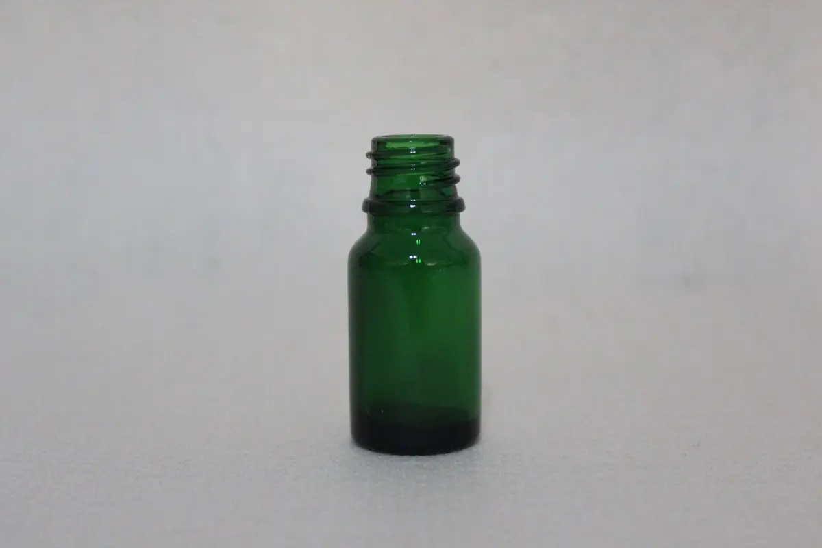
Units and reference temperature
Glass packaging drawings are normally in millimetres, with one decimal place for a functional bore dimension. An older drawing in inches should be converted before it goes out for quotation, so the tolerance is restated in metric terms and not carried over as a converted fraction.
Name a reference temperature as well. Soda-lime glass expands by roughly nine parts per million per degree, so a twenty millimetre bore shifts by only about four micrometres over a twenty degree swing, far less than mould wear or ordinary forming variation. The point of stating it is procedural: it closes off one argument and commits both sides to measuring a stabilised bottle, not one still warm from the line.
How the bore interacts with each closure or insert
An internal dimension means something only in relation to the part that meets it. How a drawing figure turns into a functional result differs by component family, and that is what tells you how much tolerance is worth buying.
Lined screw caps
A lined cap never seals on the bore. It compresses a liner onto the ring of glass between the bore edge and the outer edge of the finish face. The bore sets the inner limit of that ring and therefore its width. If the top of the bore flares beyond the drawing, the ring narrows, the liner bears on less glass, and the pack copes poorly with variation in torque, liner thickness and rim flatness. The symptom is a leak with a sound thread and a sound cap.
Top-face flatness feeds the same seal. Torque compresses the liner evenly only on a planar face; a face that rocks crushes the liner on its high side and leaves the low side slack. The check is a rocker or wobble reading with the bottle upright on a flat surface. A torque reading will not reveal it, which is why leak investigations confined to the capping head can drag on.
Plugs, orifice reducers and pourers
These seal radially on the bore. What matters is interference: bore diameter at the seating plane less plug diameter at that plane. That squeeze creates both the seal and the retention force. Neither tolerance is meaningful alone. A plug held to plus or minus five hundredths of a millimetre and a bore held to plus or minus fifteen hundredths can produce a gap in one pairing and an insert that refuses to seat in another, while each supplier demonstrates that its own part conforms. A sound specification states the interference range.
A pourer adds one complication. Its spout projects, so any offset between bore and thread axis is magnified into a visible lean; the spout then dribbles down the neck and leaves a ring on the shoulder. The same offset pushes a lined cap off centre during capping and shows up later as cross-threading or a closure that is hard to open. Neither symptom obviously implicates the bore until a neck is sectioned and measured.
Dropper assemblies
A dropper loads three features together. The pipette barrel needs clearance through the bore, so an undersized or oval bore makes it bind and can shed glass particles as the surfaces rub. The collar seats on the top face or on an internal ledge, so ledge depth sets how high the pipette tip sits above the bottle base and whether the collar grips. Concentricity decides whether the collar sits square; a tilted collar is the usual reason a dropper draws unevenly from bottle to bottle. Many complaints filed as glass quality turn out to be bore dimension problems.
Parameter, failure mode, gauge and specification wording
| Bore parameter | Parts that load it | What goes wrong when it drifts | How to inspect it | How to state it |
|---|---|---|---|---|
| Internal diameter at the sealing plane | Radial-seal plug, pourer base, orifice reducer | Weeping around the base of the insert; insert drops out in transit | Go and no-go plug gauges checked against a calibrated master ring | Nominal with both limits, the mating part's outside diameter, and the interference range that results |
| Internal diameter at the seating plane | Dropper pipette barrel, filler nozzle | Barrel binds and scrapes glass, or rattles and draws unevenly | Internal bore gauge or three-point micrometer at a set depth below the sealing face | A clearance range against the barrel diameter, with the measuring depth printed beside it |
| Minimum bore through the throat | Filling nozzle, powder dosing head, tablet chute | Nozzle cannot enter; product bridges in the neck and fill weight scatters | Your own production nozzle passed through sampled necks, supported by a plug gauge | A minimum diameter derived from the largest tool inserted, kept separate from the sealing-plane figure |
| Roundness (maximum minus minimum diameter in one plane) | Plug, orifice reducer, any radial seal | Intermittent leak that shifts position as the bottle is turned | Air gauge scan, or three-point micrometer at three orientations reported as a spread | Maximum ovality in millimetres at the seating plane, the plane fixed by depth from the sealing face |
| Concentricity to the thread axis | Pourer spout, dropper collar, lined cap | Leaning spout and product on the shoulder; collar seated on one side; cross-threaded cap | Sectioned neck on a profile projector or optical comparator, referenced to the thread axis | Maximum total indicator reading against the thread axis, with the datum feature named |
| Depth of the seating ledge below the sealing face | Dropper collar, orifice reducer, plug flange | Insert bottoms out before its seat, or stands proud and blocks the cap seal | Depth micrometer with a bridging foot, or a sectioned neck on the projector | Sealing face as datum, two-sided depth tolerance, and resulting pipette tip clearance above the base |
| Taper over the first few millimetres | Straight-shank plug, stopper | Seal forms at the wrong plane, lets go under pressure, or jams and cannot be pulled | Projected bore profile from a section, or readings at two set depths compared | Diameter at two defined depths, which fixes the draft with no separate angular tolerance |
| Flatness of the top sealing face across the rim | Lined screw cap, lug cap gasket, induction foil liner | Leaks at a torque that seals a flat-faced bottle; liner crushed on one side | Dial indicator on the rim with the bottle upright on a granite plate, or an optical flat under monochromatic light | Maximum rocker in millimetres across the rim diameter, plus the torque used for the leak test |
| Internal surface: mould seam, chill wrinkle, stone, knot | Dropper pipette, plug, anything that rubs the bore | Glass particles in the product, abrasion on the insert, uneven insertion force | Backlit visual check against a written defect standard, with a bore scope for the throat | Defect classes with maximum sizes and permitted counts; sample size and acceptance level from an attribute sampling scheme such as ISO 2859-1 |
| Bore edge at the sealing face | Cap liner, induction foil seal | Chips and flakes on the rim, liner cut in capping, fragments in the product | Visual check under defined lighting, with a chip depth check on suspect pieces | No chipping at the bore edge and a maximum flake size, written into the incoming inspection plan at an agreed AQL |
Four specification errors to catch before ordering
Treating the finish code as if it covered the inside. A drawing with a finish code, a capacity and a height has not specified the bore. Two plants quoting that code can ship different bore diameters and both comply. Where an insert is part of the pack, the internal figures belong on the drawing.
One nominal diameter, no depth, no limits. A bare nominal reads as a target, and plants variously treat it as a minimum, a maximum or a mid-point. Risk in a hole runs both ways: oversize ruins a radial seal, undersize blocks the filler. A one-sided limit therefore tends to under-specify. Give both limits and note what each one protects.
The wrong datum. Depth from the sealing face, from the shoulder and from the mould parting line are three separate measurements on one bottle. A ledge depth with no datum gets made to an unintended value, and because the error is systematic it repeats through the entire order.
Tolerancing the bore in isolation. This is the most wasteful of the four. Pressed glass can hold an internal diameter to plus or minus a few hundredths of a millimetre, but the effort is thrown away if the plug it receives is forgiving. Conversely, a wide bore tolerance does no harm with a compliant seal and is fatal with a rigid one. The interference window worked out from both drawings tells you how much precision to pay for.
Gauges for incoming inspection and for disputes
Bore is awkward to inspect: it is internal, short, transparent and reflective. Four instrument families handle nearly everything, and none substitutes for another.
Go and no-go plug gauges are the quick option for a receiving dock. The go plug, sized at the minimum allowed bore, must reach the seating depth; the no-go plug, sized at the maximum, must stop short of passing the sealing plane. The result is pass or fail, operators need little training, and every carton on a shift can be checked. The weaknesses are that it reads one diameter, reveals nothing about ovality or concentricity, and accepts a bore that is round at the gauge plane and distorted elsewhere. Gauges wear too. A go plug that has drifted undersize will accept a bore that is truly too small, so the set needs a calibration interval and a master ring.
A bore gauge or three-point internal micrometer returns a number, which is what a supplier dispute or a trend chart requires. It reads a single plane, so roundness means repeating at three orientations and reporting the spread. It needs a gentle hand, since glass marks and a tilted gauge measures a chord. In hand-held use a three-point instrument generally repeats better than a two-point one, which helps when two people measure the same bottles.
An optical profile projector or measuring microscope is the reference for geometry. A sectioned neck is projected against an overlay or CAD template, and diameter, taper, ledge depth, bore edge radius and top face angle are all read off one image. Nothing else shows practically whether a bore is straight or drafted. Use it for first article approval, mould qualification and escalated disputes. It is destructive, as the neck must be cut and the cut dressed so a burr is not mistaken for geometry, which rules it out for routine work.
Visual inspection covers surface condition. Backlighting with a defined source, a defined working distance and a written defect standard picks up seams, chill wrinkles, small stones and chips that dimensional gauges miss. In a long neck, a bore scope or small LED borescope light gives a direct view of the seating ledge. Take sample size and acceptance level from an attribute sampling scheme such as ISO 2859-1, choosing the AQL by what a defect would mean in your product, not by what is easy to inspect.
Keep other test families separate. Third-party food contact testing under EU 10/2011 or FDA 21 CFR, where the market calls for it, can use the same samples but evaluates the material and does not stand in for a dimensional check. Internal pressure resistance and thermal shock resistance have their own methods, such as ISO 7458 and ISO 7459, and are not bore tests.

A five-part bore specification
A requirement that holds up through a change of plant, mould or staff is one written in a fixed form. Five short parts are enough:
- Identification. Finish code, nominal capacity, bottle drawing revision and internal neck drawing revision, cross-referenced so an outdated cap drawing cannot be paired with a new neck drawing.
- Datum statement. Sealing face as primary datum; thread axis as the secondary reference for concentricity.
- Parameter table. Each required figure with nominal, upper and lower limit, measuring depth and unit.
- Pairing data. Outside diameter, or diameter range, of every inserted component, and the interference or clearance window the combined tolerances give.
- Acceptance method. Gauge type, sample size, frequency, acceptance level and required gauge calibration.
Two additions keep the document in use. State the reference temperature and conditioning, normally a bottle cooled to room temperature and not taken straight from the forming machine, because a warm neck gives a reading nobody can reproduce later. And state what happens to an out-of-limit result: rejection, a hold for joint measurement, or release under concession. A limit with no agreed response gets argued over once the goods have left. Treat all figures as ranges to confirm by measuring the first article, never as values lifted from an earlier project with a different neck.
When a drawing change will not solve it
Bore stays a specification matter while the parameters sit within what pressed glass holds economically, the insert comes in a range of sizes, and a single plant is involved. It turns into a sourcing matter in three cases:
- The interference window is narrower than forming can hold over a production run. The remedy is a different component, a compliant seal in place of a rigid one, or a redesigned neck.
- Two candidate plants both meet the drawing, yet your component suppliers cannot absorb the assembly variation between them. That usually points to placing neck and closure under one set of drawings held by one party.
- The insert is proprietary and its tolerances have not been disclosed. The bore then has to be designed backwards from the component.
Our first step in each case is to gather four documents: the neck drawing with internal parameters, the component drawing with its limits, the capping or insertion process setting, and the leak or retention test result that defines acceptance. With those on the table the interference window can be calculated, and it becomes clear which party has to move. For the container side, the general glass bottle range is the starting point.

Questions that belong to neighbouring topics
Bore work pays off once the thread is fixed, the component is chosen, and the open issue is whether the two fit repeatably on a filling line. Three related questions are handled separately:
- What the digits of a finish code mean, how the T, E, H and S dimensions are defined, and which closure fits which neck are covered in the guide to thread finishes.
- A built pack that leaks at the closure while the bore is within specification is a seal load problem, and the variable to adjust is the torque window described under cap torque testing.
- Limits on body diameter, height and capacity form a separate dataset, set out in tolerance standards for the whole bottle.
Bore finish FAQ
Is the bore the same thing as the neck finish?
No. They sit on opposite sides of one wall of glass. The finish is external: thread form and the nominal diameter a closure matches. The bore is internal and governs inserts, pipettes, pourers and the inner edge of the sealing band. Both need to be on the drawing.
What bore tolerance should I request?
No universal figure exists, and a number quoted without the component is guesswork. Derive the interference or clearance window from the component's tolerance band first, then divide it between bore and component so the glass keeps a realistic share. A requirement tighter than forming can hold economically can only be met by sorting, which changes the commercial terms.
How should an incoming shipment be checked?
Routine acceptance uses a go and no-go plug gauge set verified against a master ring at a fixed interval, with a bore gauge reading on a few pieces for the record and a backlit visual check for seams, stones and chips. Sectioning and projection are held back for a first article, a mould change or a dispute.
Can a bore with the right diameter still leak because it is out of round?
Yes, and it turns up often in insert leak investigations. A radial seal relies on contact around the full circle. An oval bore of correct average diameter presses hard along its long axis and loses contact on the short one, so the leak seems to travel around the insert as the bottle rotates. That movement is the mark of ovality, not of a diameter fault.
My dropper scrapes and sheds particles. Glass defect or bore problem?
Generally both. An undersized, oval or off-centre bore makes the barrel rub, and the rubbing creates the particle; the geometry is the cause and the particle the symptom. Section a few necks and overlay the projected bore profile on the pipette barrel diameter to see whether clearance was ever adequate.
Should top-face flatness be part of a bore specification?
It is a top-face property, but it belongs on the same neck drawing. The bore edge and the face together define the band a lined cap seals on, so specifying one without the other leaves the seal to chance.
What should I send to get a useful answer on bore requirements?
Send the neck specification, which may be no more than the finish code plus any internal dimensions you hold, and the type of component going in: plug, dropper, pourer, orifice reducer or lined cap, with its drawing, datasheet or diameter range if available. Contents, fill volume, closing or insertion equipment and destination market help where they are settled. From that we can say which parameters deserve a tolerance and which can stay at normal forming limits, which datum and depth definitions to print, what interference or clearance window to aim for, and which gauge, sample size and acceptance level make the requirement checkable at goods-in.