A closure compatibility test has to prove four things separately: the pack seals, the cap goes on and comes off inside a torque window, the end user can open and reclose it, and the cap sits square on the neck. No single method covers all four, so a sound programme combines a hand trial, torque measurement, a direct leak method and a transport or ageing step, and it draws samples from across the tolerance range instead of from one nominal bottle. A cap that spins on and lands on the finish has cleared only the shallowest of those checks.
The four acceptance criteria
Fit belongs to the whole system: glass finish, liner, closure shell, capping machine and the journey afterwards. Each criterion below can pass while another fails, which is why they are judged one by one.
- Seal. Product stays in, and air, moisture and oxygen stay out, for the full shelf life and distribution route. You cannot confirm this by eye. Leak paths tend to show up only once the pack has been through a temperature swing, a pressure change or vibration, so the test needs a time element.
- Torque. Application torque sits inside one measured window, and removal torque sits inside a second window after storage and shipping. They are different numbers with different consequences; recording only one gives half a result.
- Opening. The intended user can manage the first open, the tamper-evident band breaks away cleanly, and the pack keeps its seal through several reclosures.
- Alignment. The cap seats concentric with the bottle axis, with no cocking, so the pack looks properly closed and not almost closed.
A fit test answers a mechanical and sealing question only. It does not check decoration, it does not measure glass strength, and it does not replace food contact paperwork. Migration, declarations of compliance for cap and liner, and the regulatory status of the pack in its destination market are a separate discipline, even if the same supplier is in the room.
Interfaces to name before writing the test
Measure the wrong dimension and the test will approve a leaking pack, so list the interfaces first.
The glass finish
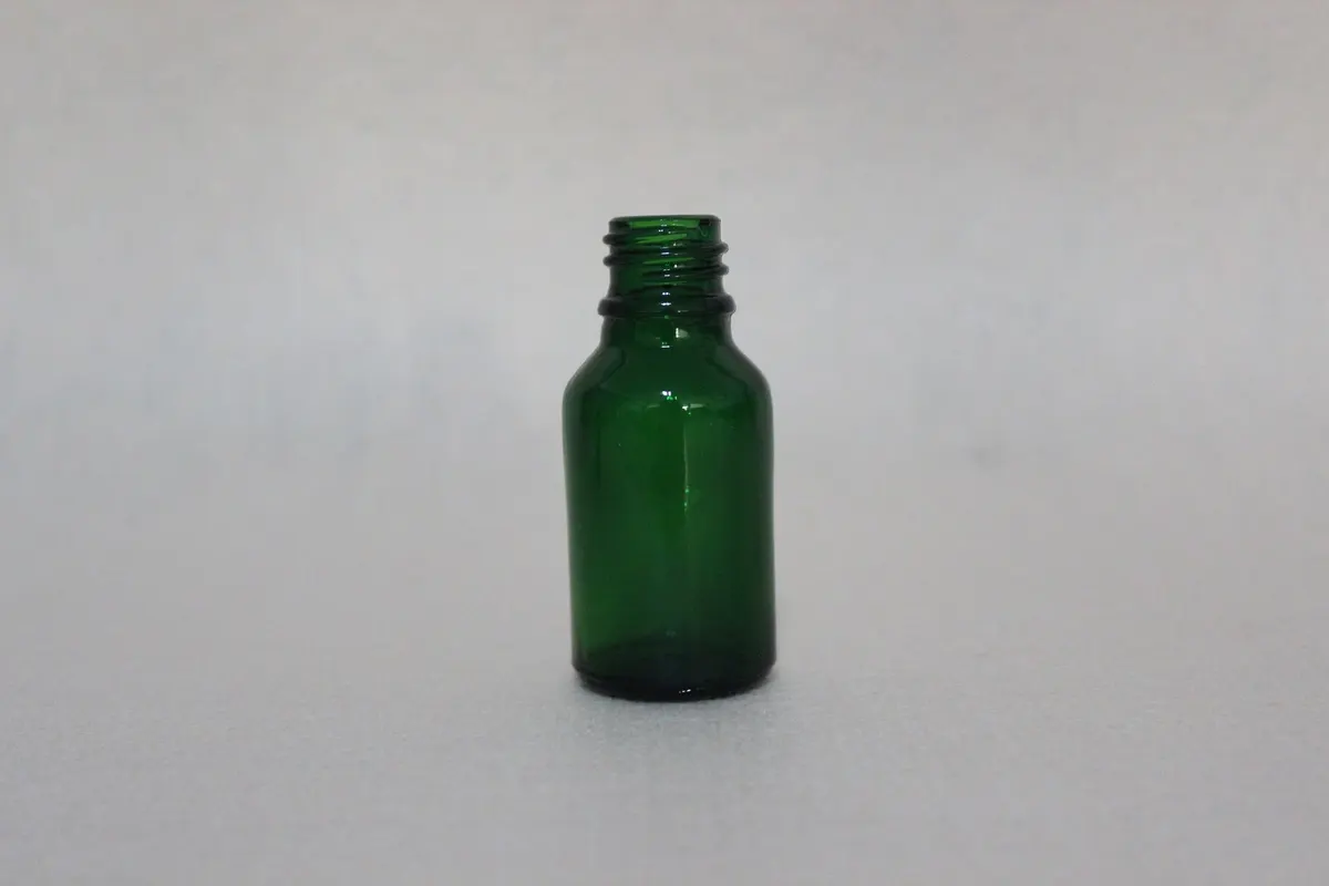
A neck finish usually carries a code such as 28-400, 38-400 or 43-400. The leading number is the nominal diameter in millimetres; the digits after it identify the thread and height family. Suppliers do not apply the convention identically, and glass and plastic differ again, so treat the code as a pointer and the drawing as the authority. Our reference on reading and measuring neck finish codes covers the vocabulary in detail.
Four finish measurements carry most of the risk:
- Thread diameter decides whether the cap thread engages and how many turns it takes to seat.
- Thread form and lead-in decide whether the cap starts square or cross-threads on a fast line.
- Finish height and turn count set how much engagement is there to carry the load.
- The top land, the flat rim the liner bears on, makes the seal. Its width, flatness and squareness to the axis all matter; a chipped, wavy, low or tilted rim beats even a flawless cap.
When a plug, stopper or dropper seals inside the neck, the internal bore becomes a fifth interface with its own tolerance logic.
The closure and its liner
The cap side has four measurements of its own: shell internal diameter, internal thread form, the depth and concentricity of the liner seat, and how the liner compresses. The liner is where glass and closure physically meet, and it is the part most likely to mask a mismatch. A thick, soft liner swallows a finish that is slightly out of specification; a thin or hard one exposes it at once. That is why one bottle can pass with one cap supplier and fail with the next when the glass never changed.
The capping event
The last interface is an action, not a dimension. Chuck, torque setting, head alignment and speed determine how the parts behave when they meet at production rate. Identical components can give different packs on different lines, so a bench test at hand speed has examined only half the system.
Test methods and the defects each one finds
The methods fall into four families. Each has a blind spot that another family covers.
Hand trial
A trained operator screws caps onto a sample set, feels the engagement, counts turns to seat, checks the gap beneath the skirt and looks for squareness. It needs no equipment and removes the hopeless options quickly: wrong thread family, a cap one size off, binding threads, a liner that has dropped out of its seat. It measures nothing, though, and two operators rarely agree on when a cap is fully home. Use it to build a shortlist and never as the final check on a specification.
Torque measurement
A calibrated tester logs application and removal torque on a stated sample count at stated intervals after capping. This converts feel into data and exposes what hands miss: over-tightening that deforms the liner, a head tight enough to split the shell or crack the tamper band, a loose head whose removal torque collapses within a day, and the gradual decline caused by stress relaxation in the liner. On multi-head cappers it also shows head-to-head spread, a frequent hidden source of field complaints. Which window to accept, and how to record it, is covered in our guide to application and removal torque testing; we deliberately publish no window here because it depends on cap, liner, contents and fill temperature.
Leak and pressure methods
Only this family examines the seal directly. Pressure or vacuum decay instruments check whether a closed pack holds a differential. Immersion in water or a vacuum chamber looks for bubbles streaming from the finish. Dye penetration puts coloured solution at the sealing line and checks whether any reaches the inside. A headspace or oxygen ingress measurement asks whether the gas inside changes with time, which is what matters for contents that oxidise. Together they find an uneven rim, a liner material that does not suit the product, a liner that holds in the sample but creeps at the real fill temperature, and a cap that is tight yet bears on a broken sealing surface.
Simulated transport and time
A transit sequence, commonly drawn from the ISTA series, puts a case or pallet through vibration, compression, drops and temperature cycling in a set order. It creates no new defect. It brings forward the latent ones: liners relaxing, caps backing off half a turn, tamper bands cracking, bottles scuffing each other, leaks that wait for a journey. It is the one method that tests fit against time, and the one most often left out. Packs that leak in a customer's warehouse are generally packs that skipped it.
Method comparison table
Read the table as a menu for building a programme. Relying only on the rows that need no instruments finds the trivial defects and misses the serious ones.
| Method | Defects it exposes | Samples and equipment | Pass criterion | When to run it |
|---|---|---|---|---|
| Hand trial fit | Wrong diameter or thread family, binding, cross-threading, absent or shifted liner, cap that refuses to seat | Ten to twenty bottles and caps from one production lot; a trained operator; no instruments | Matches a written description of correct engagement and an agreed number of turns to seat | Shortlisting, ahead of any tooling commitment |
| Application and removal torque | Too much or too little torque, distorted shells, cracked tamper bands, spread between heads, removal torque fading with time | Twenty to thirty capped samples per head or cavity; calibrated tester; fixed measuring interval | Both figures within the agreed window, reported as a spread across heads and not just an average | Tooling sample, production trial, routine batch checks |
| Pressure or vacuum decay | Leak paths between rim and liner, a non-sealing rim, too little liner compression | Conditioned capped samples; decay instrument with the right test head | Pressure loss below a stated maximum over a stated interval, with the limit fixed beforehand | Tooling sample and production trial |
| Immersion and dye penetration | Bubbling at the finish under vacuum, liquid crossing the seal, hairline channels | Capped samples; vacuum chamber or dye bath; a dye that suits both glass and cap; rinse station and inspection light | No steady bubble stream; no dye inside after the set immersion and rinse | Tooling sample; auditing a suspect lot |
| Headspace or oxygen ingress | Slow ingress, permeable liners, seals that degrade after temperature cycles | Headspace gas or oxygen instrument; samples stored at set temperatures for set periods | Headspace change inside a limit chosen for that product's sensitivity | Tooling sample, ahead of any shelf life commitment |
| Transit simulation (ISTA series) | Relaxed liners, backed-off caps, cracked bands, abrasion, post-journey leaks | Complete case or pallet of filled product; a laboratory equipped for the procedure | No leaks, cap movement within tolerance, bands intact, pack still readable and saleable | Pre-production, ahead of the first shipment |
| Drop and impact | Dislodged caps, cracked shells, rim chips that turn into leaks, band failure | Filled, capped samples; set drop height, orientation and landing surface | Pass or fail for each drop position against a described acceptable outcome | Pre-production; again if pack weight changes |
| Line trial at production speed | Cross-threading, cocked caps, drifting torque, rejects, damage from the capper | The filler's capper running at rate; a sampling plan spread over the run | Rejects under an agreed limit, with torque and seal sampled from start to finish | Production trial, ahead of commercial release |
| Reclose and multi-open cycling | Seal lost on a second or third opening, worn threads, damaged liners, bands that tear badly | Capped samples; a fixed count of open and close cycles; torque and seal readings before and after | Seal intact and closing torque inside an agreed band once the cycles are complete | Tooling sample for reusable or reclosable packs |
| Temperature and humidity ageing | Liner creep and compression set, shell dimensions shifting, seals failing in hot or damp storage | Climate chamber; capped samples; readings at time zero and every interval | Torque drift under a stated maximum and no leak when the ageing period ends | Ahead of any shelf life or distribution promise |
Points to settle with the supplier for each method
- Hand trial: the finish code and drawing behind the sample set, and whether the caps came off the production tool.
- Torque: the window the closure maker gives for that liner, and how the capping head is verified and locked.
- Decay: test pressure, interval, and the ambient conditions assumed by the threshold.
- Dye and immersion: dye type, immersion time, rinse routine, and whether that dye is allowed in a food area.
- Headspace: whether the plant can run the storage arm or the buyer holds the samples and reports back.
- Transit: which procedure in the series reflects the actual route.
- Drop: a height representing real handling, and which orientation counts as critical.
- Line trial: whether it runs on the buyer's line or a comparable machine, and what gets recorded.
- Cycling: how many openings the product really sees in use, usually more than buyers expect.
- Ageing: the temperature and humidity profile of the destination, including any hot transit corridor.
Designing for the tolerance stack
Packs that pass testing and then fail in production have mostly been tested at nominal. Production delivers a spread, and the pack must work at whatever combination turns up. Three bands stack on each other.
| Band | What varies | Typical width | Consequence for the test |
|---|---|---|---|
| Glass finish | Thread diameter and form, finish height, rim flatness, rim width | Wider than buyers tend to assume, since multi-cavity moulds differ from cavity to cavity | Sample across cavities and across the start, middle and end of a run |
| Liner | Thickness, density, compressibility, recovery | Usually the widest | Characterise the liner over the full glass band, not at one point |
| Closure shell | Internal diameter, thread form, seat depth, thread-to-seat concentricity | Usually the narrowest in a well-controlled cap | Require the cap to fit the glass band at its worst case |
Two conforming bottles off one pallet can lie at opposite limits of the finish tolerance. Gob weight and mould temperature shift during a run and the finish shifts with them. Pulling every sample from the first bottles off the line therefore tests a single cavity, not the mould.
The liner involves a trade-off. A soft liner tolerates more glass variation but relaxes fastest and sheds removal torque. A hard, thin liner keeps torque and forgives less. Choosing between them means deciding how much of the stack the liner must absorb, and that decision belongs in writing. Ask a liner to close a wider finish band than it can, and it will pass at sampling and leak at the limits.
Because the cap is usually the tightest part, people wrongly treat it as the reference and blame the glass. We recommend the reverse arrangement: specify the finish tolerance the mould can actually hold, oblige the closure supplier to fit that band, and have the liner characterised across it. If each of three suppliers works to a private nominal, the assembly carries three errors added together and no one owns the result.
Two effects sit above the dimensions. Hot filling warms and softens the liner, and as the pack cools both the shell and the headspace gas contract, so removal torque read straight after capping is not what the customer will feel. Load is the other: packs squeezed in a case, pallet, container or chiller shelf see forces a bench sample never does. Ignore both and a test will approve a pack that behaves differently a week later.
Adapting the test to liner and contents
The liner must resist the product chemically and still close the gap mechanically. A liner that suits the chemistry yet is too stiff to bridge the tolerance fails one way; one that seals well but swells in the product fails the other. The programme has to look for both.
| Liner type | Where it is used | What to watch in testing |
|---|---|---|
| Board or pulp with coated facing | Dry, low-risk products | Limited barrier and recovery; unsuited to aggressive contents or long ambient life |
| Foam (polyethylene or similar) | Finishes with noticeable variation | Compression set: the foam settles, load drops, removal torque follows |
| Induction heat seal (foil and film) | Hermetic seal with clear tamper evidence | Seal forms by heat and pressure, so sealing temperature, dwell, pressure and rim cleanliness matter alongside torque |
| Polytetrafluoroethylene or silicone faced | Products that attack other materials | Generally harder, which pushes the burden back onto finish tolerance |
| Silicone and rubber-like | Good recovery, repeated opening | Odour transfer and the supporting documents the buyer will need |
Contents shift the requirement again. Oils, solvents and the terpenes in essential oils may swell a liner or pull components out of it, so compatibility must be checked on the actual product. Acidic and acetic products attack certain facings and coatings. A high alcohol content alters the solubility conditions once more. Dairy and other protein-rich products are chemically gentler, yet the pack must survive washing and the cap must add no odour the product could pick up. Carbonated products need pressure retention, which normally moves the choice from a plain screw cap to a crown or another pressure-rated design tested on a different basis.
In practice, run the test on real product, or an agreed simulant, at the true fill temperature, then hold it for a time that stands in for shelf life. Room-temperature water is useful in development for spotting gross mismatch and is a weak basis for release.
Once the question becomes what migrates into food, the framework is food contact law and not fit: FDA 21 CFR in the United States; in the European Union, EU 1935/2004 as the framework regulation plus EU 10/2011 for plastics including the cap and liner; and LFGB for Germany. The component supplier issues these documents. Establish early which part carries which declaration and whose name is on it.
Holding fit steady in routine production
Writing the specification is the easier half. Moulds wear, gob weight and mould temperature wander during a run, cap tooling wears, liner lots vary, heads slip out of adjustment, and a pneumatic or servo head can shift its own torque setting across a long shift. A programme that ends at the sample has a specification and no control.
One sampling plan, three inspection points
Write the plan down. For attributes, the usual basis is ISO 2859-1 with an agreed acceptable quality limit, stating lot size, sample size, acceptance and rejection numbers and switching rules. Which plan you pick matters less than agreeing it in advance and using the same one for incoming glass, incoming closures and the assembled pack. Three plans yield three verdicts on one defect.
Instruments where the decision is made
Thread and finish height gauges let incoming inspection clear glass without a laboratory, and a gauge set spanning the acceptable range makes the judgement documented. A torque tester rotated over several heads at a fixed frequency tells you more than repeated readings on one, since heads usually differ from each other by more than any one drifts. An end-of-line leak indicator matched to the product's sensitivity ties the two key measurements together.
Charts and a reaction rule
Plot results instead of merely accepting or rejecting. A control chart of removal torque reveals a trend before a limit is crossed; a gradual fall points to liner compression set or a head losing its setting. One reading out of limits is an event, whereas seven readings moving in one direction is a cause, and the chart turns a supplier dispute into a discussion of evidence.
The plan also needs a reaction rule for out-of-limit results: how much stock goes on hold, whether the last good check marks the quarantine boundary, who is told, how the head or mould cavity is isolated, and what proof is needed to restart. Without it, a measurement becomes a report, and a report controls nothing.
Three common failures and the order to investigate
Leaks between rim and liner
The most frequent problem, and often chased in the wrong sequence. Work through it like this:
- Inspect the rim. No closure can rescue a sealing land that is chipped, wavy or tilted.
- Confirm the liner is present, seated, the specified material and compressed within its intended range.
- Check the application torque the pack really received; a correctly set head can still under-deliver.
- Only then question the finish dimensions, measuring rim and sealing surface against the finish drawing.
Caps backing off or removal torque fading in storage
- Suspect the liner first: compression set and stress relaxation, since any loaded liner gives up some load with time.
- Then over-application. It feels like the cautious direction, but squeezing a liner beyond its elastic range destroys the recovery the seal relies on.
- Then thread engagement, reduced either by a finish with fewer usable turns or by a cap applied at an angle so part of the thread carries everything.
- Finally thermal cycling, which alters cap dimensions and internal pressure and can loosen a pack that left the line tight.
Cocked caps, ragged tamper bands and cross-threading at speed
This group is nearly always a machine issue before a component issue. Start with head alignment and chuck condition. Next look at bottle squareness and finish tilt against the base, then the thread lead-in and thread start position, which govern how dependably the cap catches at speed. Cavity-to-cavity mould variation comes last. Changing the glass to cure a capper alignment fault buys a new mould and keeps the defect.
What to send for a test plan
Send three things together:
- The neck finish. A code if there is one, plus the drawing or measured thread diameter, finish height, rim width and sealing land condition. Caliper readings over several bottles beat a code because they show how much the finish really moves.
- The closure. A physical sample, or a drawing with shell internal diameter, thread form, seat depth and liner material and thickness.
- The contents. Product, fill temperature and treatment route, which between them decide which liners are candidates at all. Add destination market, transport mode and required shelf life.
From those we can draft a test matrix, a method and pass criterion for each test, the stage where each belongs, and the drawing points to fix before tooling or a production trial is committed, so the first shipment is not the first real test. For a pack already in production with a complaint, add the defect description, how many packs are affected, where they sat in the run, and the storage or transport history. Those details show whether to begin with the capping head, the liner lot or the finish.
Two related questions are handled elsewhere. Inside diameter and the wall a plug, stopper or insert seals against are covered under bore finish and internal neck sealing. For a standard Boston Round where the real question is which stock caps, droppers, sprayers and pumps suit the neck, use our lookup on pairing Boston Round necks with stock closures.
Frequently asked questions
Is a cap fit test just a leak test?
No. Leak testing is one part and speaks only to sealing. A pack may hold pressure on the bench and still be unsaleable with a cocked cap, or meet its torque figures and leak through an uneven rim. Torque, openability, band release, concentricity and survival through storage and shipping each need their own method.
How many samples make a fit result meaningful?
For development, at least twenty to thirty capped samples per closure or per capping head, taken from more than one mould cavity and from the start, middle and end of a run. Fit is a distribution; ten samples from a single cavity describe that cavity only. For release, size the sample from a written plan, normally ISO 2859-1 with an agreed acceptable quality limit for attribute sampling of visible and functional defects.
Can water stand in for the real product?
For screening out gross mismatch, yes. For a release decision, no. Oils, solvents, alcohol, essential oils, acids and carbonation each affect liner materials differently, and fill temperature and viscosity change behaviour after capping. Use the actual product or an agreed simulant, on the actual capper, and hold the samples long enough to represent shelf life.
How does a 400 finish differ from a 410 for fit purposes?
The numbers name thread families, which in practice means the available turns and the drawn thread form. Fewer usable turns leave less thread to carry the closing load and less margin for a cap applied slightly off angle. A taller or differently shaped thread changes liner compression at full seat. Naming is not fully consistent across suppliers and materials, so write the test against the drawing and measured dimensions.
Why would a cap that fitted the sample leak in production?
The sample was a nominal point and production is a range. The first seals to fail are at the edges of the stack: a cavity at one limit of finish tolerance, paired with a liner from the thin end of its band, closed by a head set a little loose. Specify the band and test across it instead of testing the best case.
What equipment does a filling plant need for routine fit checks?
A calibrated torque tester, thread and finish height gauges for incoming glass, a simple leak indicator suited to the product, and a documented sampling plan with a reaction rule. That is enough to hold a process and keep a control chart. Characterising a new pack is development work: decay instruments, dye or immersion tests, climate ageing and transit simulation are normally run at tooling sample and pre-production stages by the glass plant, a third-party laboratory or the filler.
How can I tell whether glass or closure is at fault?
Isolate the variable. Measure bottles spanning the run and the cavities against the finish drawing, and caps spanning the closure lot against theirs. Then cross them by putting the extreme glass with the extreme cap. If the extremes fit, the components are workable and the capping process is the problem. If particular pairings fail, the band is too wide and one tolerance must tighten. Assigning blame before that crossing test is guesswork.