A glass bottle needs an induction seal when the cap liner alone cannot be trusted to do one of three jobs: hold liquid back when the pack lies on its side, show that the neck has not been opened, or keep oxygen, moisture and aroma out for the whole shelf life. The seal is an aluminium membrane welded to the top of the neck through a plastic cap, so it works only with a closure that lets the magnetic field through and a glass sealing land that is clean, flat and continuous. Whether the weld is sound is read from the peeled membrane, a peel force figure and a leak or vacuum decay test run after transport as well as at the line.
How the weld is made and when a liner alone will do
The bottle is filled and capped first. It then travels under a sealing head that carries a coil. The coil's alternating magnetic field induces a current in the aluminium layer of the membrane sitting inside the cap, the foil heats up, and a heat-seal coating on its lower face melts onto the glass land, the flat ring at the top of the neck. The consumer later unscrews the cap and peels the membrane away.
A compressible liner works differently. It seals because the cap squeezes it against the neck, so its performance rests on torque applied weeks before and on how well the liner material springs back. A welded membrane relies on neither. That difference produces three tests for whether the membrane is worth having:
- Containment. Oil, vinegar, syrup, sauce or tincture can weep at the thread if the bottle is laid down, inverted during filling or dropped into a carton. A weld stops that. A pack that never leaves the upright position and is used up within days can often manage with a liner.
- Opening evidence. An intact membrane under the cap shows that the neck was closed at the filling site and left alone since. Pharmacy, supplement and food channels frequently require this commercially as well as for safety, which is why the membrane stays on packs whose closure would hold the product anyway.
- Barrier. Aluminium stops moisture, oxygen, aroma and light. A foam or silicone disc does not. If shelf life depends on excluding oxygen or keeping a volatile aroma in, the membrane is there for barrier, not for leakage.
If none of the three applies, the membrane adds expense and nothing else. If any one applies, the pack needs it.
Seal types for glass bottles compared
The comparison below deliberately contains no power, time or force values. Workable settings depend on the particular cap, glass, product and machine, and a published figure stripped of those inputs turns into a specification nobody can hit. Numbers belong in the sealing trial record for the specific pack.
| Seal type | How it seals | Layers and their roles | Closure and line consequences | Typical use | Checks |
|---|---|---|---|---|---|
| Liner only | No weld; torque compresses the disc onto the land | One compressible disc doing both sealing and barrier | No sealer; the capping torque window is the sole control | Dry goods, very short shelf life, packs never inverted, low-risk non-liquid fills | Torque window, containment after storage, no wicking into the disc |
| One-piece induction wad | Wad rides in the cap; the field heats the foil and the lacquer welds to the land with the cap on | Backing cushions against the cap roof, foil heats and blocks, lacquer bonds to glass | Needs a plastic shell, correct torque before sealing and a wad in every cap | Default for liquids under plastic screw closures where sealing and opening evidence are both required | Unbroken weld ring, peel force, leak or vacuum decay, clean land |
| Two-piece seal with separate membrane | A loose membrane is placed on the neck, the bottle is capped and the weld is made through the cap | Membrane holds foil and lacquer; the disc in the cap is only a re-closure gasket | Extra placement step before capping; stray or missing membranes are a risk; copes well with wide mouths | Wide-mouth jars, closures that hold a wad poorly, lines already placing inserts | Membrane present and centred, full weld ring, disc still seated |
| Tabbed peel membrane | Standard weld plus a tab outside the weld ring for lifting by hand | Added tab layer and an unlacquered tab zone; weld ring and barrier unchanged | Tab must stay off the land and within reach; cap height and thread must leave room for fingers | Wide-mouth jars, large diameters, any pack where a flat foil disc is hard to grip | Tab adhesion and lift force, weld ring undisturbed, tab still free after transit |
| Barrier-enhanced membrane | Standard weld with further film layers selected for the product | Usual backing and foil; additional barrier or lacquer layers manage oxygen, aroma and product contact | May need more energy, since more material lies between coil and lacquer | Oxygen-sensitive, aroma-critical or long-shelf-life fills such as oils and extracts | Headspace oxygen or moisture, aroma retention, peel force, corrosion resistance in acid or salt fills |
| Membrane under a dispensing closure | Same weld, but the foil lies further from the coil under a tall disc top, flip top or pump | Standard seal layers; the closure adds a plug or spout above or into the neck | Coupling falls with distance; a plug touching the membrane passes torque into the weld | Dispenser packs poured or pumped once the membrane is off | Energy reaching the foil at that distance, plug clearance, weld ring after capping |
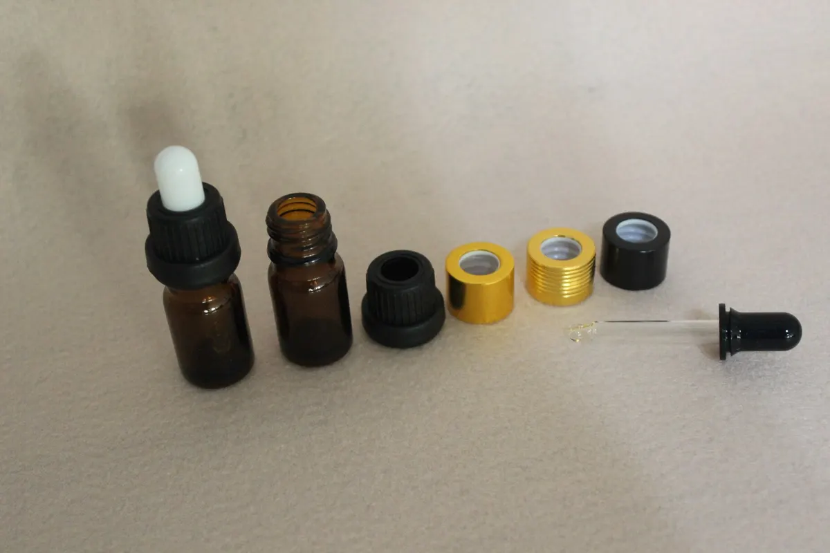
What each layer of the membrane does
A membrane is a stack of three layers with separate duties. Treating it as a single item is the source of most specification mistakes.
Heat-seal lacquer: the bond
This polymer coating on the bottle-facing side is the only layer that adheres to glass. Its thickness, softening behaviour and grip on both foil and glass determine whether the pack holds. It also touches the product for the life of the pack, and a ring of it remains on the neck after peeling. It therefore has to suit the contents and the food or cosmetic contact rules of the destination market, not only the sealing process.
Aluminium foil: the heater and the barrier
The foil absorbs the field and becomes the heat source, then serves as the barrier once the weld exists. A continuous foil couples evenly and blocks moisture, oxygen, aroma and light. A creased, pinholed or perforated foil may still keep liquid in while letting oxygen through, and under an acid or salty product it can corrode and release the seal from within.
Backing: the cushion
Usually foam or paper, the backing sits between the foil and the cap roof. It neither seals nor blocks. It presses the foil evenly onto the land during heating, makes up for the shape of the cap roof and protects the membrane during capping. Too thin, and the lacquer does not touch the full ring; too thick or stiff, and the weld lifts on one side. It is also the layer most often swapped for a cheaper grade without a re-check of the seal.
The practical upshot is that sealing and barrier are independent properties. A pack can pass a leak test and miss an oxygen or aroma target, or hold vacuum and still corrode, so the specification must state both. Acid, salty and high-alcohol fills also raise compatibility questions for the lacquer and foil; the chemistry and migration evidence are dealt with alongside compressible discs in our guide to choosing a cap liner material.
Which closures can be sealed through
The cap sits between coil and foil, and it also governs what happens to the membrane later, so seal type and closure are chosen as a pair.
Plastic screw caps. Polypropylene is effectively transparent to the alternating field, which makes PP the standard closure material for this process. The shell keeps the wad concentric, and opening and re-closing are ordinary consumer actions. On products opened many times, the disc left behind in the cap takes over as a re-closure gasket and should be specified for that role.
Metal shells. Aluminium roll-on caps and tinplate lug or twist-off closures cannot be sealed through. A continuous metal layer couples with the field itself, shields the wad and heats up, scorching the cap and its decoration while the lacquer gets no usable bond. Never run a metal cap fitted with an induction wad under a sealer and expect a seal. The realistic options are to weld the membrane to the neck in a separate operation before the metal cap goes on, to switch closure material, or to rely on a compressible liner. This is settled at the packaging concept stage; no head setting changes it.
Disc tops and flip tops. These are normally polypropylene and can carry a wad, with two geometry cautions. A taller dispenser body puts the foil further from the coil. And a plug or spigot that reaches into the bore may rest on the membrane, feeding cap torque and stacking load straight into the weld. Check plug clearance above the membrane, not just the thread fit.
Pumps and trigger sprayers. These are the hardest: tall, often built from several materials, and frequently impossible to seal through. The bottle is usually sealed under a plain screw cap with the dispenser fitted afterwards, or a membrane is placed and welded as a separate step before the dispenser is added. Write the sequence into the line documentation, because fitting the dispenser before sealing means there is no seal at all.
Closure dimensions and appearance vary by product family. The caps used on olive oil bottles show how tamper evidence, pouring behaviour and seal type get decided together, and if the container is still open, the glass bottle collections list the neck finishes a membrane would have to weld to.
Sealer settings: power, dwell, coil and head height
A sealer puts a set amount of energy into the foil, governed by a few controls that affect one another. Understanding how they interact lets a line be set once instead of being adjusted every shift.
Power and dwell. Power is the energy available; dwell is how long the cap stays beneath the coil. On a conveyor, dwell is a product of coil length and line speed, so a faster line needs more power or a longer coil. The two cannot simply be traded. A brief, intense pulse heats the foil surface and lacquer before warmth has spread around the ring, leaving a partial ring. A long, mild application warms the entire wad, softens the backing and can distort the cap, leaving a scorched ring.
Coil and head height. The coil must suit the cap diameter. Oversized, it spreads the field; undersized, it concentrates energy at the centre. A head mounted too high loses coupling, and one too low may hit the cap. Heads that handle several diameters exist, yet each size change is a setting change to be written down, not judged by eye.
Cap condition at the coil. A weld forms only where lacquer is pressed onto glass. The cap must be on, square and torqued before the bottle reaches the head. A loose or cross-threaded cap, torque under the window, or a wad out of position removes that pressure, and no sealer setting restores it. Many apparent sealing faults are capping faults, and the torque window and its sampling are covered in our guide to capping machines for glass bottles.
With a membrane in place, the liner's role shrinks. The membrane seals and blocks; the disc cushions during sealing and afterwards acts as a re-closure gasket. Changing liner material on an induction-sealed pack therefore usually means validating a gasket, a far smaller exercise than validating a primary seal.
Four checks that show a seal is sound
A membrane that looks sealed proves nothing. The checks worth having are those that can be done beside the line and repeated after shipping.
- Read the weld ring. Peel a membrane and look at it and the neck. A complete weld leaves a light, even haze of lacquer across the full width of the land with no gaps, wrinkles or bare patches. Bright, clean faces, a lift at one point or a scalloped edge mean a partial bond. It uses up one bottle and belongs in the start-up routine, since it reveals drift before packs ship.
- Measure peel force. Pull the membrane with a force gauge at a defined angle and log both the force and how the bond lets go. The value must be high enough to withstand handling, stacking and pressure swings, yet low enough for the intended consumer, which is a genuine limit on wide diameters and tabless membranes. Bonds generally strengthen over the first days and weeks, so a reading taken an hour after sealing is not what the customer will feel.
- Test for leaks. Pressure decay, vacuum decay or submersion in a vacuum chamber finds paths through the weld that the eye misses. It catches marginal seals, provided it is run across the tolerance band on packs filled at production temperature with the real product or an agreed simulant, not on a few ideal samples at nominal settings.
- Follow up after storage and transit. Repeat the peel and leak checks after a short accelerated storage period or a transit simulation to a recognised sequence such as those ISTA publishes. Weighing samples held at elevated temperature is the simplest way to spot slow loss that an ambient leak test will not show.
Failure signatures and their causes
Six faults explain most failed seals, and each leaves a recognisable mark.
| Fault | What you see | Where to look |
|---|---|---|
| Product on the land | Membrane bonded on one side of the ring, free across the contaminated arc; the most frequent cause of a partial seal | Filling: nozzle height, fill speed, anti-foam measures, an inspection point after the filler |
| Too little energy | Holds liquid but peels easily, or a faint ring | Power too low, line faster than the head was set for, head too high; often follows a speed or cap-size change |
| Too much energy | Charred lacquer, browned or deformed backing, blistered or curled membrane, scorch mark on the cap top | Power too high, line too slow, head too low |
| Missing, displaced or wrong wad | Bottle leaves the sealer unsealed yet looks normal from outside | No wad, wad fallen out or tilted, plain disc in place of a membrane; add a wad-presence check ahead of the sealer |
| Cap loose, cross-threaded or off-square | Seal absent or thin all the way round, commonly across a batch | The capper, not the sealer |
| Glass land out of condition | Rejects that seem random until measured, then follow the finish | Chips, cracks, land out of square, decoration run onto the top face, ridge at the mould seam |
A scorched seal tends to be weaker than a correct one, and repeated scorching harms the closure too, so turning power up to cure a weak bond goes the wrong way.
Two habits prevent most repeat trouble. Keep a trial record per cap-and-bottle combination giving the power, line speed, head height and coil size that produced an acceptable ring; nothing else makes settings repeatable after a changeover. And when a seal fails, examine the peeled membrane before adjusting anything, because the ring's shape separates energy, pressure, contamination and glass faults more reliably than guesswork at the control panel.
Loads on the membrane in transport and storage
A welded membrane resists tension well and shear poorly. It is thin foil, not a structural part, and it meets several loads between the filler and the customer.
- Pressure change. Warm loading, a hot climate or a mountain pass all shift internal pressure. A good weld lets the membrane dome and relax. A marginal weld experiences that pressure as a peel force from inside and shows seepage at the thread or a lifted spot, which is why an ambient leak test does not qualify a pack for travel.
- Stacking. Top load passes through the cap and the bottle shoulder, not the foil. The danger is indirect: a cap crushed by a point load no longer keeps the wad in contact. Use pallet and carton patterns that spread load across the cap, check top load on the packed case, and never count on the membrane to bear any of the stack.
- Vibration. Transit vibration can lower the applied torque of a screw cap. Once the cap backs off, the membrane is the only closure and is exposed to knocks through the loose cap. Measure torque after a transit simulation as well as at capping.
- Dents and creases. A crease distorts the aluminium and costs barrier performance at that line even while the leak path stays shut. Wide diameters are more exposed than narrow necks, which is one argument for a tab: the consumer lifts the membrane instead of picking at it with a fingernail.
- Warehouse cycling. Cartons held in a damp store and then loaded into a hot container go through temperature and humidity swings nobody sees on the pallet. Properly sealed packs come through; marginal ones fail, and it only shows on arrival.
For these reasons the acceptance criterion should be written against the tolerance band and proven through a cycle, not against one good sample on production day.
Information to include in an enquiry
Describe the pack as it will actually run. Each item below changes the recommended seal type or the sealer setting; none is a refinement.
- Contents. Viscosity; whether oily, acidic, salty or alcoholic; whether it foams; claimed shelf life and storage conditions. Thin, low-viscosity, oily or foaming products splash and film the land during filling, and surface tension and nozzle accuracy affect how hard the seal will be to make.
- Fill temperature and filling method. A hot fill loads the cap with vapour and heat; a chilled fill draws heat out of the bond as it forms. Both alter the energy required and how the membrane behaves as the pack cools.
- Bottle. Neck finish, glass colour, and the land itself: width, flatness, squareness to the axis, any mould seam, chip or coating, and any decoration that could reach the top face.
- Closure. Material and shell type, any plug or spout entering the bore, cap height above the neck, and the torque window the capper holds.
- What the seal must achieve. Leak protection in a stated orientation, first-opening evidence, a barrier against oxygen or aroma, or a combination. Say also how the consumer should open it: an easy-lift peel, a tab and a child-resistant peel are different choices, and market and product category decide between them.
- Line. Whether the sealer is a stand-alone conveyor head, the conveyor speed range, whether speed changes mid-run, whether several cap sizes share one head, and who owns the settings. A sealer with no accountable owner drifts.
With that in hand we can propose a seal type, a membrane structure with the sealing layer and the blocking layer named separately, the requirement the closure design must meet, starting settings for a sealing trial, and the checks to record at start-up and after transit. For a metal cap, a pump or a tall dispenser, ask for the alternative sequence as well, since the fix is usually a different order of operations and not a different membrane. Quantities, pricing and timing are confirmed per project once the specification is complete.
Frequently asked questions about induction seal bottles
Is a cap liner the same thing as an induction seal?
No. A liner is a compressible disc inside the cap that seals under load against the neck. An induction seal is an aluminium membrane welded onto the neck by heat generated in its own foil. When a pack has both, the membrane is the primary seal and barrier, and the disc serves as cushion and later as re-closure gasket.
Can a bottle with a metal cap be induction sealed?
Not through the cap. The metal shell couples with the field, shields the wad and overheats, so the decoration burns and the lacquer does not bond. The membrane has to be welded to the neck before the cap is fitted, or the closure changed to plastic, or the pack left with a liner only.
How strong should the peel feel to the customer?
It should survive handling, stacking and transport pressure changes while remaining removable by hand. Both limits shift with neck diameter, since lifting force rises with the width of the weld ring, and with whether a tab gives something to grip. Allow for the bond gaining strength in the days and weeks after sealing when setting the target.
How can seal integrity be checked without a laboratory?
Peel a sample and read the ring, pull another with a force gauge to get a number, and run a leak, vacuum decay or vacuum chamber submersion check on packs filled at production temperature across the tolerance band. Add a weight-loss check on stored samples, or repeat peel and leak tests after a transit simulation, to confirm the seal lasts beyond the line.
How do I tell a contamination fault from an energy or capping fault?
The peeled membrane distinguishes them. Contamination leaves the ring free in one local arc. Low energy gives a full but faint ring. A loose cap gives a ring that is uniformly thin. A glass defect produces rejects that track the finish.
What should I do about a burnt membrane?
Reduce the energy reaching the foil: the power is too high for the line speed, the line is running slower than the head was set for, or the head is too close to the cap. Because a burnt bond is generally weaker, adding power never cures it. A written settings record for each closure and bottle combination is what keeps the adjustment from being repeated at every changeover.